
Letting Go

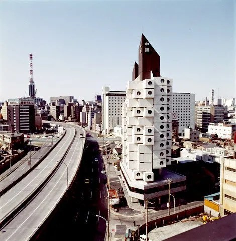
The 1974 building we know as Nakagin Capsule Tower was marketed by Nakagin Mansion Co., Ltd. as Nakagin Capsule Mansion <Ginza> (中銀カプセルマンシヨン <銀座>) or, more simply, as Business Capsule (ビジネスカプセル). I recently bought what looks like a newly-printed facsimile of the original marketing brochure for the building. Its yellowed paper is actually a high-quality photograph of yellowed paper. The cover image is from when visualizations were those hand-drawn and colored perspective drawings known as “artists’ impressions”. From July 10–July 12 last year, there was a MoMA exhibition titled “The Many Lives of Nakagin Capsule Tower”1 so I expect the reprint might have something to do with that. My freshman year was 1974. MoMA and I must both be trying to keep alive as long as possible, memories of a time when each new building seemed to promise an optimistic and fantastic future for architecture. Here’s that brochure.


I’m not keen to repeat things that have already been said2 but on the other hand there are too many new things being said – not least in books having ten chapters of 7,000 words. I think I prefer to say things that aren’t new, but which simply haven’t been brought to anyone’s attention before. This brochure was the first time I’d ever seen all floor plans together, and with respect to the site boundaries. There’s evidence of much thought.
The drawing below shows the capsule naming conventions used by Kurokawa’s office. As an example, B8-4-A refers to Tower B, Level 8, and the next number is the Capsule Number (numbered clockwise for Tower B and anticlockwise for Tower A and beginning at the 6 o’clock position). The letter designation A, B, C or D refers to Unit Type. The capsule type we’re most familiar with from photographs is Unit Type A where the entrance door is along the end wall with the bathroom on the right but there’s also a variation with the bathroom on the left. Capsules B4 and B5 below, are these two variations mirrored – as are B6 and B7. Type C has the entrance on the side wall and facing the bathroom. However, Type C also has two variations. Capsules A5 and B8 are one variation while B5 on the 11th floor is a side entry variation, mirrored. Capsule A7 is Type D and has the entry on the side-wall and the window on the opposite site wall. Capsules A8 and B1 are both Type B with the entry on the end wall and the window on the side wall. Type B and Type D capsules are always found in the same positions on each level. To create this representation of mass production needed one type of core with left and right variations, and four types of units, two of which also have left and right variations.

Type A: 29 Left (20.7%), 26 Right (18.6%)
Type C: 24 Left (17.1%), 31 Right (22.1%)
Type B: 18 Left (12.9%)
Type D: 12 Left (8.9%)
There are 55 Type A capsules and 55 Type Capsules but the most common is the Type C Right variant even though the Type A is the conceptual model. The Type C was needed for special cases such as
- A2 and B2, and A3 and B3 where it is not possible to have a window on the end wall
- A7 and B8 where an end-supported capsule would not fit within the site
Views
Type D and Type B are special cases with the window in the variant position to avoid directly looking into or being looked into from neighbouring windows as much as possible, and also for as long as possible because even in 1974 it would have been obvious that, sooner or later, a building would be built hard up against the shared boundary (to the bottom, in the plan). Type D A7 and Type B A8 and B1 are examples where having a side window is better than and end window. It’s incorrect to use the word “stacked” when units are attached in a vertical line but, in the image on the left below, the rightmost stack of units are Type B and the next stack in are Type D. They are like this on all floors and for the same reason. The best views were probably to be had from higher-level capsules A6 and A5 looking along the expressway rather than across it. The image at right below is from an A or B, 4 or 5.


Site utilization
Eight is generally regarded as the maximum number of units that can be accessed from a single core. This layout of a Hong Kong Housing Corporation tower is bi-axially symmetrical. Nakagin Capsule Tower can’t be bi-axially symmetrical because Capsules A2, A3, B2 and B3 would have to have a side window and that would mean a obvious variation on the front elevation. Not good. But even if that compromise were made, the building would become too long for capsules B1 and B8 to fit on the site. Even though there’s still plenty of site (to the right), capsules B1 and B8 would be even less able to fit if capsule A7 were Type A. Most buildings are designed to fit their site but the only concessions this one makes to the size and shape of its site are the variant Type C unit B8 and the variant Type D unit A7. Type B units A8 and B1 are variations most likely made for reasons of illumination rather than view.


Dimensions
If we accept that the cores can’t be made any smaller, and that one side of the square core must accommodate the width of two Type A capsules, then the dimensions of those capsules (and thus the entire building) are determined by where capsules A7 and B8 bump up against their respective boundaries. Capsules A4, A5, B4 and B5 are already hard up against the boundary. This is one of those problems where a change in one dimension means a change in every other dimension. I remember somebody (Kurokawa?) saying the capsule internal area of about ten square meters is about the same size as a traditional Japanese tea ceremony room. That was all that was said, and it was left to us to infer that it was a good thing.
Fire escape
Whether a unit connects to the core as an side-entry capsule or an end-entry capsule is therefore not completely arbitrary. The A7 Type D (with the side entry and side window) is necessary to shift the building as far to the left of the site as possible, and the B8 (side entered) Type C is necessary to squeeze in eight capsules per level per tower. But even this is not always the case for “bridge levels” 6, 9 and 12 that are missing capsules A2 and B2 to allow for passage between cores, almost certainly to offer an alternate means of fire escape. Both staircases are mildly terrifying even without a fire but are in cores that are mirrored left-right. This means that one staircase is clockwise and the other is anticlockwise. People don’t behave rationally when escaping fire so, if the bridges are there solely for reasons of fire-escape, it would make more sense for both staircases to be one or the other so that people escaping fire could continue in a straight line when reaching the other landing instead of having to run to the other side. Fire escape routes should have as few surprises as possible. Whether the cores are simply mirrored (as they are) or rotationally symmetrical (as I’m suggesting) the four units opening off the elevator landings would still be at the same levelbut the capsules in position 5 in Tower A would be one third of a floor above the elevator landing and those in position 5 in Tower B would be one third of a floor below. I suspect the staircases are mirrored solely for compositional reasons.3In the middle image below4 you can see the hoods that some of the rear-facing windows have to stop internal overlooking to windows in that position for reasons of less external overlooking and/or better illumination.


Servicing
The service risers are in the corners of each core, as shown in this typical plan and the images. This means all services have to pass through the structure in order to service the capsules. This was a fundamental and never-resolved problem with Metabolism but the immediate problem is that only some bathrooms (such as A1, A4, A6 and A8, and B1, B4, B5, B6 and B7 – a little more than half) have their bathrooms adjacent to the risers. The Level 8 arrangement of B4-B5-B6-B7 is the best possible for servicing. All Type C bathrooms (such as in A5, B2, B3 and B8) couldn’t be further from their risers. This complicates drainage and requires some contrivance such as can be seen between the capsules in the lower three images, and most likely contributed to the building’s demise. Looks like a leak. Not only do the drainage pipes and their connectors need to be designed with possibly multiple connectors to accommodate the different routes to the shafts, the pipes have next to no slope and this means that water will not drain quickly or completely, making an already less than ideal situation more so.5


Access
In the plan above, fifteen risers are shown for the Tower A stairwell and seventeen for the Tower B stairwell. This can’t be right. Even 17 risers means a F/F of 2.55m for standard 150mm risers. And once we subtract the 20cm gap between capsules and allow for a 10cm thick structure, the internal height becomes 2.1m ?! Judging from the photographs, the are 15 x 20cm maybe? Yep – 2.1m6. It’s not high, but higher than your average Japanese tea room.

Construction
We hear much about the structure of Nakagin and how the capsules are “hung” on the towers but how exactly? Information is scarce for such an important aspect of the building. Here’s all I could find, and it’s not very reassuring. First, the service risers aren’t shown in the drawing on the left so we’re none the wiser regarding drainage and water and electricity supply.7 The different positions and alignments of the bathrooms relative to the service risers means that the standardized trays beneath each bathroom must contain pipes with either flexibility in the actual (PVC?) pipes and or their connections. Sounds like a recipe for failure sooner than later.8The drawing on the right corresponds to what we see in the middle image. The capsules are lifted into position so their two “feet” align with their supports (“shoes”?). Above, four bolts secure the capsule in place. Much faith is placed in the strength of both the supports and the bolts but I learned the high-tension bolts were tightened from within the capsules. This site9 has some excellent construction photographs and drawings and tells me that the steel supports were encased in concrete that, upon demolition, was found to have cracked in places. Uh-oh.


This combination of structure and construction also places much faith in the rigidity of the capsule but all I could find on that was this diagram from Metalocus10 that tells us “the capsules were fabricated in a shipping container factory and have a lightweight steel truss structure clad with ribbed steel panels and coated with some rust-prevention paint and a weatherproof covering called kenitex11 that’s supposed to last for 25 years”. It lasted 35. Neither the capsule support system nor the plumbing and servicing were designed for regular inspection, let alone replacement.

Aesthetics
Even if the bolts and supports were still good for another 25 years, the capsules were initially placed in position starting from the bottom and working up. They were never going to be replaced other than by removing them all, starting at the top, and replacing them all with new ones starting again at the bottom. It was never going to happen so we shouldn’t be surprised it didn’t. Instead, we wanted to believe it could yet, we have the apparently arbitrary orientations of some units to represent how independent each unit was. We now know the Type C units were specially designed to make the building footprint fit its site, but their other and more remembered use was to suggest that the capsules were more independently interchangeable, and that the building was only one arbitrary aggregation out of many – which of course it was. These (side-entry) Type C units replacing (end-entry) Type A units for no obvious reason on the front of the building make us not want to notice how regular the rest of the building really is.

• • •

• • •
Notes:
- https://www.world-architects.com/zh/architecture-news/found/a-micro-exhibition-on-micro-dwellings ↩︎
- https://en.wikipedia.org/wiki/Nakagin_Capsule_Tower ↩︎
- Text added 21 March 2026. ↩︎
- By Dick Thomas Johnson from Tokyo, Japan – Nakagin Capsule Tower, CC BY 2.0, https://commons.wikimedia.org/w/index.php?curid=110078748 ↩︎
- Text added 21 March 2926. ↩︎
- https://japanese-creative-books.com/product/architects/nakagin-capsule-tower-the-last-record/ ↩︎
- more photos here: https://nakagintower.tumblr.com/ ↩︎
- Text added 21 March 2026. ↩︎
- The site is a fan site and the homepage (https://capsuletower.net/) links to original construction drawings and much other information, some of which is here after having been posted to other sites. ↩︎
- https://www.metalocus.es/en/news/nakagin-capsule-tower-tokyo-1969-72-kisho-kurokawa ↩︎
- https://kenitex.co.za/ ↩︎
Recently Revisited:
Nothing this week.
Share this:


Graham McKay
says:I think you’re spot-on when you say so many buildings rely on layers of words to justify our continued attention. As someone responsible for teaching the history or architecture and design, it’s always good to ask why the same comments have to be propagated. I was surprised that Nakagin had so much else that could have been said about it, but never was.
Roque Perez Pareja
says:Very interesting, it makes me reflect on how many buildings seem fragile in their established greatness. They rely on layers of words and concepts to defend their value, rather than standing convincingly on their own physical presence.